Combining Function and
Position
The Positron Emission
Tomography/Computed Tomography Scanner
The medical Imaging
Device of the Future?
By Jack Wells
Abstract
Separate PET and CT scanners are widely
used in the clinical environment to produce functional and anatomical images
respectively. The dual scanner is a recent innovation and combines both scans
into one examination. Information from both scans can be aligned more easily
onto one image. The device has led to
significant improvements in patient administration. Most importantly it has
improved the accuracy of tumour detection and localisation. Studies revealed
that the hybrid scanner aided tumour identification in 56% of lung cancer
patients. In addition it was discovered that the increased accuracy of the
device led to changes in radiation treatment planning in 40% of the patients
sampled. However the accuracy of the images is limited due to the finite
movements of the patient during the CT scan.
The PET/CT scanner is a tumour detecting imaging system that combines
anatomical and functional information to produce a comprehensive picture of the
internal workings of the body.

CT image PET image Combined Image
Figure 1: Metastasis of the
liver and pelvis (1)
As illustrated by
figure 1, this technique can produce images with greater clarity then either
method alone. This is of obvious importance to the detection of tumors and
significantly influences the effectiveness of hospital treatment. Furthermore,
the scanners have additional advantages that benefit the clinical environment.
I will begin by explaining
the principles behind PET and CT. The second section will discuss image
registration, how the information from each device is combined. Next, I will
detail the design and features of the scanners. Finally, the benefits and
disadvantages of the system are reviewed and the current state of the field is
summarized.
Computer Tomography (CT) Imaging
The principle of CT relies on synchronised movement of the source and detector to produce an image in the plane of the patient. The word tomography originates from the Greek τομοs (slice) an dγράφειυ (to write) [20]. A set of thin x ray lines is used to scan the required area to be imaged. The process is then repeated for a large number of angles. This results in attenuation readings for all possible angles and distances from the required plane. These results can then yield to the reconstruction of the actual attenuation at each point.

Figure 2 [21]: A schematic illustration of the progressive generations of CT geometries. Each set of lines from the source to detector represents a view. The axis of rotation is always the centre of the subject.
A. First-generation, translate-rotate pencil beam geometry. B. Second-generation, translate-rotate fan beam geometry. C. Third-generation, rotate-only geometry. D. Third-generation offset-mode geometry.
The standard protocol for the dual scanner is a low dose spiral CT [24].
The X-ray tube rotates around the patient. The patient is then moved through
the central axis of the rotation. Therefore in the frame of the patient, the
tube possesses a helical orbit.
X-ray source
X-rays are produced when energetic electrons are stopped in a
material with a high atomic number [22]. Electrons are emitted from a heated
tungsten filament. These are accelerated via a potential difference in a vacuum
to a tungsten target (molybdenum is used to produce a lower energy spectrum for
mammography). The source must provide a very short, high energy burst of x-rays
so the image will not be blurred by patient movement. In addition the size of
the source must be small to ensure the edges of the image appear sharp [22].
This must be achieved despite the fact that 95%-99% of the electron energy is
transferred to heat within the target. Therefore a rotating anode is used to
dissipate the heat over a wider area. In addition the target is inclined to
ensure a small focal spot whilst maximising the area available to the incident
electrons. The x-ray spectrum produced is made up of characteristic and bremstrahlung (continuous) radiation. The maximum energy of
the x-rays is proportional to the accelerating voltage and the intensity is
proportional to the current and is reliant on the voltage squared. The target
material and filtration due to the surrounding casing further shapes the outgoing spectrum.
The focal spot, energy spectrum and intensity are the main variables which must be considered for an effective x-ray source. The focal spot determines the spatial resolution of the image as overlapping beams will result in blurring of the views. The energy of the incident photons establishes their penetrative ability. X-rays with greater frequencies are more likely to be detected but are less able to distinguish between different tissue types. Increasing the intensity enhances the signal to noise ratio at the detector but raises the dose to the patient. Furthermore greater intensities require a larger focal spot. It is clear that the design of the source must account for a compromise of these variables to produce optimal performance. Modern CT scanners have focal spots of 0.5mm to 2mm.
Interactions of x-rays within the
patient and detector [22]
At low photon energies within high atomic
number materials, the photoelectric effect predominates. The Compton Effect
dominates as the incident energy increases in all materials. The reliance of
the interactions upon the physical properties of the tissue and detector is the
essential aspect of CT imaging that allows images to be produced. The
probability of a photoelectric interaction taking place is proportional to the
atomic number of the material to the power of four. The probability of
Conventional X-ray systems tend to use a simple film/screen combination. However, CT detectors are made up of gas proportional chambers or rows of scintillator and photomultiplier pairs. The operation of the latter is described in the next section. This allows information to be stored digitally which is essential for the superposition of images. In 1994 George Charpak received the Nobel Prize for physics for the multi wire proportional chamber (MWPC). A Russian group based in Novosibrsk, later collaborated with George to develop a medical imaging system based on the MWPC. The most unique aspect of such a devise is that it detects each X-ray photon as a single event rather then the superposition of a large number of interactions. As a results x-ray photons can be clearly distinguished from noise. Thus the signal to noise ratio is reduced and a high quality image is produced with reduced dose to the patient. The chambers contain pressurised Xenon gas. Within the chambers are a series of wires with a high positive potential. The outside of the chamber is negatively charged. The wires are roughly 1mm apart. Incident X-ray photons will interact with the Xenon gas and create charge pairs. Under the influence of the electric field these accelerate towards the wires. Consequently they undergo multiple collisions creating more charge pairs and thus produce a charge cloud. This interacts with the wire to produce a pulse which is counted if its magnitude is sufficient. A computer records the number of counts on each wire every 30ms. Gas ionisation chambers have high stability and inherent collimation. However the majority of CT devises relay on scintillator/ photomultiplier pairs as they can be made into large arrays and a re relatively cheap.
As a consequence of scattering effects, the
greatest test of x-ray imaging is the detection of low contrast details.
Consequently tissue types with linear attenuation coefficients differing by
less then 5% are often indistinguishable. This is where the PET scanner is
invaluable as physicians attempt
to identify pathological effects.
Positron Emission Tomography (PET)
 Figure 2 : A schematic diagram of a PET scanner (3)
The main attribute of PET imaging is its capability to trace radioactive labels metabolised in the tissue to provide information about its biochemical and physiological behaviour (4). The most common positron emitter is 18F. This is administered as a radiopharmaceutical, named fluorodeoxyglucose (FDG). Cancer cells tend to accumulate more glucose in comparison to other tissues. Consequently, there will be higher concentrations of FDG in tumours. The radioactive nuclei then decay by positron emission [25]. A nuclear proton decays into a positron and a neutron. The atomic mass of the atom does not change but its atomic number decreases by one. An ejected positron then annihilates with an electron. This produces photons which travel in opposite directions. Each photon has energy of 511kev, equal to the rest mass of the respective ferminions. The finite time window used in coincidence detection involving two surrounding detectors placed opposite to each other provides an efficient mechanism of electronic collimation (3). Scattered photons do not tend to arrive within the coincidence time window and thus are rejected. Once 100,000 or more events are recorded, the distribution of the tracer is computed using tomographic reconstruction techniques [25].
A scintillation crystal converts the gamma rays to visible light photons. On average, it requires 30eV of light to produce a visible light photon in NaI (the most commonly used scintillation material) [26]. Therefore the crystal is around 10% efficient. The precise energy required varies between resulting in a spread in the number of visible photons produced for a given energy absorbed. However this uncertainty is largely negated by the statistical ambiguity in the photomultiplier tube.
The photomultiplier tube converts an incoming signal of a few hundred or thousand visible light photons to an electrical signal. It consists of the photocathode and the multiplier. The photocathode is designed to produce a large number of low energy electrons whilst ensuring the outgoing current is proportional to the intensity of the signal from the crystal. An electron absorbs a visible photon. The electron then travels to the surface of the photocathode. Finally the electron escapes from the surface. These electrons are then electrically focused to collide with the first electrode of the multiplier. The acceleration of the electrons by a potential difference causes secondary electronic emission at the electrode. The multiplication factor at each junction is between 5 and 10 [26]. For each electrode there is an optimum accelerating voltage. The greater the voltage, the more secondary electrons are produced. However they originate at greater depths within the material and thus are less likely to escape. The gain is independent of the number of electrons from the photocathode from 1 up to a few thousand. Thus a linear output can be obtained from an increasing number of light photons [26].
The recent progression of new and smaller crystals, such as LSO, GSO (with better timing and energy properties), has increased the accuracy of the images (5). At this time the major clinical application of PET is tumour identification and localisation in oncology.
Image Registration
Data from both devices must be correctly combined to produce accurate images. The main condition for registering the information is that a relationship between the coordinates of the corresponding points in the two images is determined (1). This is found using a coordinate transfer function (CTF), which is a set of operators which map pixel values from one image to the other. This is illustrated by diagram 1:
The poor resolution of PET images means that they often contain few anatomical landmarks. Previously it was necessary to view them in conjunction with CT images with the patient often returning on a separate day. Reference markers, attached to the surface of the patient, were used to account for the differences in subject position. This was suitable for fixed organs such as the brain but other sections such as the abdomen are mobile and may shift position between data acquisition.
The introduction of the dual scanner has simplified image registration. The two sets of data are collected in sequence and so are intrinsically registered. As a result only the distance between the CT and PET sources and detectors must be considered.
The design and
operation of the scanner
Prior to the
introduction of the combined scanner, patients would have a CT exam on one
device and PET test on another. Figure 3 shows the design of the hybrid
scanner:
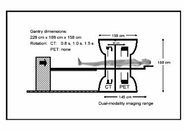
Figure 3; Design of the
scanner (6)
Firstly, the patient
is injected with a suitable dose of tracer solution depending on the extent of
the scan. This is followed by monitoring in a quiet environment at rest.
The
patient is positioned as illustrated in figure 3. Initially, a topogram is applied to calculate the scan range. The topogram is a rapid, low dose, planar x-ray exam which
identifies anatomical landmarks for positioning of the scan template (7). The
template then can be easily resized if necessary. The system is then calibrated
for the scan parameters (the patient is scanned from the ear to the mid thigh
for a whole body scan (10)) and the spiral CT begins (7). The main advantage of spiral CT is its
ability to scan larger volumes with shorter time periods. This is achieved by
connecting the tube voltage cables through a sliding contact positioned on the
rotating gantry. The x-ray tubes rotate and the patient table moves in a
continuous motion. This technique reduces patient motion, an important factor
in the hospital environment. Furthermore, spiral methods give a quicker
response to contrast media and reduce motion artifacts (interferences from
other planes of the patient) (8). Moreover, the continuity of data along the
axis of the patient aids the quality of three-dimensional construction
(9). . The bed is then moved into
position and the emission scan begins. On average, acquisition times will range
from 4-6 minutes per bed position (10). Ideally the patient should have their
arms up. This minimizes beam hardening and artifact effects. Beam hardening is
the removal of low energy photons, which reduces contrast. Given the relatively
short scanning time, the subject should be able to maintain this position for
the duration of the acquisition Patients are advised to maintain constant, shallow
breathing during the acquisition [24]. Respiratory motion often results in
mushroom artifacts above the diaphragm that are a persistent problem in CT
imaging. These problems can be further reduced by instructing the patients to
hold their breath at appropriate times during the scan. The CT dataset provides high quality,
anatomical images which are used for PET attenuation correction. This means the
scan duration of the PET/CT system is shorter then that from a single PET exam.
CT
protocols are regularly designed for individual studies on various body parts.
The combination of different CT studies in a single examination requires some
time and ingenuity to design a procedure that maintains contrast and minimizes
the acquisition time and dose to patient. This problem is less prominent in
independent imaging centers where information can be analyzed by a single
physician.
Advantages
and Limitations of the Scanner
There is
significant evidence that PET and CT, when analyzed together, increases the detection
rate of cancers. Before the introduction of the dual scanner, an abnormality
seen on PET could not be corroborated by CT because either there was no obvious
lesion or the discontinuity developed in the interim period between scans. As a
result, the interpreting physician would have to make an educated guess as to
the exact site based exclusively on the anatomical information from the PET
data. Chin et al. (12) found that by
sampling 30 patients with mediastinal lymph node
involvement the diagnostic accuracy increased to 90%. Furthermore Vandteenkiste
et al. (13) compared FDG-PET and CT images with just CT using lung cancer
patients. It was found the diagnostic accuracy increased from 59% to 87%. They
also found specificity, accuracy and sensitivity increased from 63%, 68% and
75% to 94%, 95% and 93% respectively. Based on the findings of significant
negative predicted value (false positives) using PET alone, it was discovered
that mediastinoscopy was unnecessary in 29 of 68
patients (13).
However examination
of PET and CT images by hand is laborious and vulnerable to human error (10). Before
the introduction of the dual scanner, an abnormality seen on PET could not be
corroborated by CT because either there was no obvious lesion or the
discontinuity developed in the interim period between scans. As a result, the
interpreting physician would have to make an educated guess as to the exact
site based exclusively on the anatomical information from the PET data. Martinelli et al. (14) tested more then 100 oncology
students using a prototype PET/CT scanner. They found that it yielded a more
accurate image of FDG uptake, was able to differentiate between physiologic and
pathological uptake and led to improvements in monitoring technique. Moreover
the same research group (15) discovered it led to significant improvements in
patient administration, due to the time saved in interpretation. Furthermore,
PET/CT has proven particularly useful in imaging ‘’akward’’
regions of the body such as the post-surgical abdomen and the head/neck. Kamel and co-workers (16) discovered visual FDG uptake in
the lower anterior neck in 6 of 184 patients who took part in lung cancer
staging. They also found this hybrid devise avoided the false positive effects
of PET unaided.
The possible
advantages of the dual scanner to evaluate patients with lung cancer were
investigated by Keidar et al (17). 26 sufferers were
sampled which led to improved information regarding lesion localization and FDG
uptake in 56% of the patients.
A promising
clinical role of PET/CT is in radiation treatment planning. CT alone is
relatively inaccurate in displaying the size of the tumour.
Dizendorf et al. (18) investigated the influence of
the integrated device on 30 patients receiving external beam radiation. In 30%
of the patients, the dosage was altered and changes in volume and target were
recorded in 40% of the patients.
Limitations
of the Positron Emission Tomography/Computed Tomagraphy
Scanner
One of
the main technical limitations of PET/CT is the problem caused by artifacts due
to the breathing of the patient and metallic implants. These difficulties were
examined by Osman et al. (19). They concluded
incorrect positioning induced by patient movements resulted in 6 of 285 of
those tested. They found errors occurred in liver lesions near the base of the
right lung. The group also conducted
research on the effect of metallic dental implants on the accuracy of the
images. However they found artifacts on the PET images were corrected for by
the CT scan (19).
The dual
scanner signifies a new generation of medical imaging acquisition tools that emphasize
the intricacy of multidisciplinary clinical decision making. Perhaps the most
demanding area of CT/PET is the necessity to easily display anatomical and
functional data that essentially represents 5 or 6 dimensions [24]. The failure
to efficiently interpret and navigate through information recorded by the dual
scanner is a considerable handicap to many physicians. Currently, no software
package exists that provides a user friendly interface to navigate though such
detailed, multidimensional data.
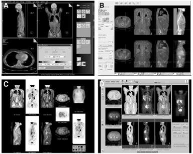
Figure 4: Examples of commercially available graphic
user interfaces of multimodality viewing software programs [24] A: Siemans B: Hermes C: General Electronic D: Philips [24]
Consequently,
image analysis and interpretation can take from 10 minutes in a standard study
to 30 minutes in a complicated case with many abnormalities and lesions. This
far outweighs the time a physician needs to deduce any irregularities from a
standard CT scan. It seems interpretation time is improved in comparison to
separate scans but is significantly greater then the single CT scan.
A
further problem with multimodality diagnostic workstations is their capacity in
storing very large data sets. Some scanners will lessen processing time by
compromising the spatial resolution from 512*512 pixels per axial slice to
256*256 or by decreasing the range of pixel values from 16 to 8 bits. This
compromises the value of the CT image. Consequently considerable processing
power is required to maintain the integrity of the image. Even then the loading
of a complete, whole body scan can take several minutes.
The
implementation of image archiving and filmless
radiology has improved the value of the PET/CT scanner significantly in recent
years. However in large institutions the logistics of sustaining an efficient
collaboration between those administering and interpreting the combined data
requires flawless communication.
Conclusion and Future Prospects
PET/CT is emerging as a preferred
method for assessing both anatomy and function of common cancers (10).This is despite
drawbacks due to the finite time of the PET scan and the inefficiency of the
display mechanisms. However, increased detection and localization accuracy and
reduced operating cost mean this hybrid device is fast overtaking separate
imagers as the tool of choice in modern hospitals (5).
As the usage increases, many of
the limitations discussed will be addressed. In particular, appropriate
protocols for different cancer types must be formulated and the application of
the devise must extend more thoroughly to neurology and cardiology. In
addition, the role of the hybrid scanner with other, more disease specific
tracers then FDG will become more prominent. Furthermore, it is essential that
designers of computer tools and specialists in image communication improve
their support of multimodality imaging. The success of PET/CT depends not only
on diagnostic improvements but on its application in clinical decision making
and patient care.
References
(1)
http://www.brighamandwomens.org/referringphysiciansnews/PET_CT.pdf
(2) Medical image analysis. Atam.P.Dhwan, Pg.62
(3)
Medical image analysis. Atam.P.Dhwan, Pg.97
(4)IEEE trans. Med imaging vol
15, 278-289, 2000. S.L Hartmann and R.L Galloway. Depth Buffer targeting for
spatial accurate 3-D visualization and medical imaging.
(5)European school of medical physics 2003. Advances
in PET (and SPECT) and some applications. Nuclear Medicine image registration.
Andrew Todd-Pokropek, UCL.
(6) http://gamma.wustl.edu/rsna03/02-Townsend-RSNA03.pdf
(7) http://www.cpspet.com/our_tech/how_petct_works2.shtml
(8)Medical Imaging physics. 4th edition.
William Henden, E. Russel Rilenour, pg 62.
(9)Hu, H.Multislice
helical CT: Scan and reconstruction. Med Phys 1999. 26.5.
(10) PET/CT applications and pitfalls. Richard.L.Wahl.M.D. Division of nucleur
medicine. John Hopkins Medical Institute,
(11) Dual modality PET/CT ‘’an imaging technology that
changes the care of cancer patients’’. John Czernin.
Department of molecular and medical pharmacology. Ahmanson biological clinic.
UCLA school of medicine. Los Angles, CA.
(12)Chin R Jr, Ward R, Keyes
JW, et al. Mediastinal staging of non-small-cell lung
cancer with positron emission tomography. Am J Respir
Crit Care Med. 1995;152 (6 pt1) 2090-2096.
(13)Vansteenkiste et all.
Lymph node staging in non-small-cell lung cancer with FDG-PET scan. A prospective
study on 690 lymph node stations from 68 patients. J Clin
Oncol. 1998;16:2142-2149.
(14)Martinelli M et al.
Survey of results of whole body imaging using PET/CT at the
(15) Kluetz et al. Combined
PET/CT imaging in oncology: Impact on patient management. Clin.
Positron Imaging. 2002;85:53-58.
(16)Kamel E, Recurrent
laryngeal nerve palsy in patients with lung cancer: detection with PET/CT image
fusion. Report of 6 cases. Radiology 2002;224:153-156.
(17)Keidar Z et al. Hybrid
imaging using PET/CT with F-18-FDG in suspected recurrence of lung cancer:
Diagnostic value and impact on patient management. [abstract] J Nucl Med 2002;43. A-144.
(18)Dizendorf et al, Impact
of integrated PET/Ct scanning ion external beam radiation treatment planning
[abstract] J Nucl Med. 2002;43:A-547.
(19)Osman M et al.
Clinically significant inaccurate localization of lesions with PET-Ct:
Frequency in 275 patients [abstract]. J Nucl Med.
2002;43 (suppl): A-116.
[20]Paul Suetens,
Fundamentals of Medical Imaging, pg 66 (X-ray Computed Tomography).
[21] Ketcham, R.A. and Carlson, W.D., 2001.
Acquisition, optimization and interpretation of X-ray computed tomographic imagery: Applications to the geosciences.
Computers and Geosciences, 27, 381-400
[22] C390(UCL,
Medical Physics Department, Imaging with Ionising Radiation-lecture
notes-Robert Speller-Latest Revision June 1998.
[23]
Paul Suetens, Fundamentals of Medical Imaging, pg 81
(X-ray Computed Tomography).
[24]Osmin Ratib, MD, PhD: PET/CT
Image Navigation and Communication, The Journal of Nuclear Medicine
vol.45 no.1 Jan 2004.
[25]Karen
M.Mudry, Robert Plonsey,
Joseph D.Bronzino, Biomedical Imaging,
sect.14-7(PET).
[26]
C390(UCL, Medical
Physics Department, Imaging with Ionising Radiation-lecture notes- Ian Cullum- sciltillation detector..
[27]
http://gsm.utmck.edu/CITDP/documents/principles_000.pdf